
![]() This chapters provides an overview on how to implement a high-availability solution according to a given network design and requirements. This includes building a resilient network with optimal redundancy for high availability. Monitoring the network using SNMP, Syslog, and IP SLA are key elements to ensure the high availability of the network.
This chapters provides an overview on how to implement a high-availability solution according to a given network design and requirements. This includes building a resilient network with optimal redundancy for high availability. Monitoring the network using SNMP, Syslog, and IP SLA are key elements to ensure the high availability of the network.
![]() This chapter also covers supervisor redundancy options such as RPR, RPR+, SSO, and NSF. For ensuring first hop gateway redundancy, the Hot Standby Router Protocol (HSRP), Virtual Router Redundancy Protocol (VRRP) and Gateway Load Balancing Protocol (GLBP) are needed. First hop redundancy protocols (FHRP) allow for nondisruptive failover between available redundant gateways. HSRP/VRRP allow for one primary router per subnet with other routers acting as standby/backup. GLBP allows load balancing across multiple gateways for the same subnet. The first hop redundancy protocols are explained in detail in this chapter.
This chapter also covers supervisor redundancy options such as RPR, RPR+, SSO, and NSF. For ensuring first hop gateway redundancy, the Hot Standby Router Protocol (HSRP), Virtual Router Redundancy Protocol (VRRP) and Gateway Load Balancing Protocol (GLBP) are needed. First hop redundancy protocols (FHRP) allow for nondisruptive failover between available redundant gateways. HSRP/VRRP allow for one primary router per subnet with other routers acting as standby/backup. GLBP allows load balancing across multiple gateways for the same subnet. The first hop redundancy protocols are explained in detail in this chapter.
 Understanding High Availability
![]() High availability is technology that enables networkwide resilience to increase IP network availability. Network applications must cross different network segments—from the Enterprise Backbone, Enterprise Edge, and Service Provider Edge, through the Service Provider Core. All segments must be resilient to recover quickly enough for faults to be transparent to users and network applications. This chapter describes the high availability concept, how resiliency is built, and how the network is designed to always offer a path between any pair of end points.
High availability is technology that enables networkwide resilience to increase IP network availability. Network applications must cross different network segments—from the Enterprise Backbone, Enterprise Edge, and Service Provider Edge, through the Service Provider Core. All segments must be resilient to recover quickly enough for faults to be transparent to users and network applications. This chapter describes the high availability concept, how resiliency is built, and how the network is designed to always offer a path between any pair of end points.
Components of High Availability
![]() High availability is an organizational objective with the goal of preventing outages or at least minimizing downtime. Achieving high availability is hard work. It takes ongoing effort and iterated improvement.
High availability is an organizational objective with the goal of preventing outages or at least minimizing downtime. Achieving high availability is hard work. It takes ongoing effort and iterated improvement.
![]() To start making progress on providing high availability requires integrating multiple components, as shown in Figure 5-1.
To start making progress on providing high availability requires integrating multiple components, as shown in Figure 5-1.


![]() The network redundancy and technology components are relatively easy to accomplish because these elements can be purchased and deployed. A traditional network designer will expect to be involved with these two aspects of high availability.
The network redundancy and technology components are relatively easy to accomplish because these elements can be purchased and deployed. A traditional network designer will expect to be involved with these two aspects of high availability.
![]() No matter how much and how well redundancy and technology are designed and deployed, high availability is not achieved unless the people component (sufficient labor pool with the right skills, training, and mindset), the process component (company expectations, change control process, and so on), and the tools component (network management, good documentation) are present. If any one of the three high-availability components is insufficiently addressed, incidents will happen and outages will occur. Initially, the network designer might not be able to fix the people, processes, and tools in an organization. Often, it takes a consultant doing a post outage design review to talk about these components and suggest changes.
No matter how much and how well redundancy and technology are designed and deployed, high availability is not achieved unless the people component (sufficient labor pool with the right skills, training, and mindset), the process component (company expectations, change control process, and so on), and the tools component (network management, good documentation) are present. If any one of the three high-availability components is insufficiently addressed, incidents will happen and outages will occur. Initially, the network designer might not be able to fix the people, processes, and tools in an organization. Often, it takes a consultant doing a post outage design review to talk about these components and suggest changes.
Redundancy
![]() Redundancy designs attempt to eliminate single points of failure, where one failed device or design element brings down service.
Redundancy designs attempt to eliminate single points of failure, where one failed device or design element brings down service.
![]() A redundant design can use several mechanisms to prevent single points of failure:
A redundant design can use several mechanisms to prevent single points of failure:
- Geographic diversity and path diversity are often included.
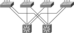
- Dual devices and links are common, as shown in Figure 5-2.
- Dual WAN providers are common.
- Dual data centers are sometimes used, especially for large companies and large e-commerce sites.
- Dual collocation facilities, dual phone central office facilities, and dual power substations can be implemented.
![]() Redundant design must trade off cost versus benefit. It takes time to plan redundancy and verify geographic diversity of service providers. Additional links and equipment cost money to purchase and maintain. These options must be balanced against risks, costs of downtime, and so on. The time and money invested in redundancy designs needs to be spent where they will have the most impact. Consequently, redundancy is most frequently found in network, data center, or e-commerce module cores, and then in critical WAN links or Internet service provider (ISP) connections. Additional e-commerce module redundancy can double up elements in the path between users and applications, and the applications and back-end databases and mainframes.
Redundant design must trade off cost versus benefit. It takes time to plan redundancy and verify geographic diversity of service providers. Additional links and equipment cost money to purchase and maintain. These options must be balanced against risks, costs of downtime, and so on. The time and money invested in redundancy designs needs to be spent where they will have the most impact. Consequently, redundancy is most frequently found in network, data center, or e-commerce module cores, and then in critical WAN links or Internet service provider (ISP) connections. Additional e-commerce module redundancy can double up elements in the path between users and applications, and the applications and back-end databases and mainframes.
Technology
![]() Several Cisco routing continuity options, such as Cisco Nonstop Forwarding (NSF) and Stateful Switchover (SSO) exist, and graceful restart capabilities improve availability. These technologies allow processor failover without a link flap, continued forwarding of packets, and maintenance of Border Gateway Protocol (BGP) adjacencies.
Several Cisco routing continuity options, such as Cisco Nonstop Forwarding (NSF) and Stateful Switchover (SSO) exist, and graceful restart capabilities improve availability. These technologies allow processor failover without a link flap, continued forwarding of packets, and maintenance of Border Gateway Protocol (BGP) adjacencies.
![]() Techniques exist to detect failure and trigger failover to a redundant device. These techniques include service monitoring for Cisco IOS IP Service Level Agreements (SLA) and Object Tracking. Object Tracking enables you to track specific objects on the network, such as the interface line protocol state, IP routing, and route reachability, and to take action when the tracked object’s state changes.
Techniques exist to detect failure and trigger failover to a redundant device. These techniques include service monitoring for Cisco IOS IP Service Level Agreements (SLA) and Object Tracking. Object Tracking enables you to track specific objects on the network, such as the interface line protocol state, IP routing, and route reachability, and to take action when the tracked object’s state changes.
![]() Other technologies also contribute to high availability. For example, fast routing convergence and server load balancers help maintain high availability. Firewall stateful failover can maintain user or application sessions across a firewall device failover.
Other technologies also contribute to high availability. For example, fast routing convergence and server load balancers help maintain high availability. Firewall stateful failover can maintain user or application sessions across a firewall device failover.
People
![]() Redundant equipment and links and advanced technology are just the beginning of high availability. In the Prepare, Plan, Design, Implement, Operate, and Optimize (PPDIOO) methodology, the people component is vitally important, too. Staff work habits and skills can impact high availability. For example, attention to detail enhances high availability, whereas carelessness hurts availability. Reliable and consistent wiring and configurations are easier to manage and troubleshoot.
Redundant equipment and links and advanced technology are just the beginning of high availability. In the Prepare, Plan, Design, Implement, Operate, and Optimize (PPDIOO) methodology, the people component is vitally important, too. Staff work habits and skills can impact high availability. For example, attention to detail enhances high availability, whereas carelessness hurts availability. Reliable and consistent wiring and configurations are easier to manage and troubleshoot.
![]() The level of staff skills and technical training are important elements when it comes to taking full advantage of redundancy. Devices must be configured correctly. Lab testing is important to understand the circumstances that activate failover, and what failover will and will not accomplish. Thoroughness in lab testing often translates into less downtime in production. For example, nonstateful firewall failover might be adequate in terms of passing traffic. However, a practical understanding of the application can show that with nonstateful failover, application sessions will lock up for an extended period of time until an application timeout causes session reestablishment. Designs that include failover must be tested for the entire system, not just for individual components.
The level of staff skills and technical training are important elements when it comes to taking full advantage of redundancy. Devices must be configured correctly. Lab testing is important to understand the circumstances that activate failover, and what failover will and will not accomplish. Thoroughness in lab testing often translates into less downtime in production. For example, nonstateful firewall failover might be adequate in terms of passing traffic. However, a practical understanding of the application can show that with nonstateful failover, application sessions will lock up for an extended period of time until an application timeout causes session reestablishment. Designs that include failover must be tested for the entire system, not just for individual components.
![]() Good communication and documentation are also important. The network administrators need to communicate with other network, security, application, and server teams. The network documentation should cover why things are designed the way they are and how the network is supposed to work. Failover behavior is complex enough that it is unwise to have to recapture failover logic and boundary conditions every time some part of the design changes.
Good communication and documentation are also important. The network administrators need to communicate with other network, security, application, and server teams. The network documentation should cover why things are designed the way they are and how the network is supposed to work. Failover behavior is complex enough that it is unwise to have to recapture failover logic and boundary conditions every time some part of the design changes.
![]() Field experience leads to the observation that if people are not given time to do the job right, they will cut corners. Testing and documentation are often the first items to be eliminated. Lack of thorough testing and documentation can have long-term consequences on the ability to maintain, expand, and troubleshoot the network.
Field experience leads to the observation that if people are not given time to do the job right, they will cut corners. Testing and documentation are often the first items to be eliminated. Lack of thorough testing and documentation can have long-term consequences on the ability to maintain, expand, and troubleshoot the network.
![]() If the design target is just “adequate” coverage, falling short of that target can lead to a poor design. Designs should be better than adequate to ensure that no part of the implementation or operation of the high-availability network is inadequate.
If the design target is just “adequate” coverage, falling short of that target can lead to a poor design. Designs should be better than adequate to ensure that no part of the implementation or operation of the high-availability network is inadequate.
![]() One other organizational recommendation is to align staff teams with services. If the corporate web page depends on staff who report to other managers, the manager of the e-commerce site might compete for staff time with the network engineering or operations manager. In most cases, the person who does the staff evaluation and provides the pay bonus generally gets most of the attention. This organizational structure can make it difficult to get routine testing or maintenance done for the e-commerce site if the staff does not report to the e-commerce manager. The owner or expert on key service applications and other components should be identified and included in design and redesign efforts.
One other organizational recommendation is to align staff teams with services. If the corporate web page depends on staff who report to other managers, the manager of the e-commerce site might compete for staff time with the network engineering or operations manager. In most cases, the person who does the staff evaluation and provides the pay bonus generally gets most of the attention. This organizational structure can make it difficult to get routine testing or maintenance done for the e-commerce site if the staff does not report to the e-commerce manager. The owner or expert on key service applications and other components should be identified and included in design and redesign efforts.
Processes
![]() Sound, repeatable processes can lead to high availability. Continual process improvement as part of the PPDIOO methodology plays a role in achieving high availability. Organizations need to build repeatable processes and gradually improve them. Tasks that are always implemented as a special one-time occurrence represent a lost opportunity to learn as an organization.
Sound, repeatable processes can lead to high availability. Continual process improvement as part of the PPDIOO methodology plays a role in achieving high availability. Organizations need to build repeatable processes and gradually improve them. Tasks that are always implemented as a special one-time occurrence represent a lost opportunity to learn as an organization.
![]() Organizations should build repeatable processes in the following ways:
Organizations should build repeatable processes in the following ways:
- By documenting change procedures for repeated changes (for example, Cisco IOS Software upgrades)
- By documenting failover planning and lab testing procedures
- By documenting the network implementation procedure so that the process can be revised and improved the next time components are deployed
![]() Organizations should use labs appropriately, as follows:
Organizations should use labs appropriately, as follows:
- Lab equipment should accurately reflect the production network.
- Failover mechanisms are tested and understood.
- New code is systematically validated before deployment.
![]() Because staff members tend to ignore processes that consume a lot of time or appear to be a waste of time, organizations also need meaningful change controls in the following ways:
Because staff members tend to ignore processes that consume a lot of time or appear to be a waste of time, organizations also need meaningful change controls in the following ways:
- Test failover and all changes before deployment.
- Plan well, including planning rollbacks in detail.
- Conduct a realistic and thorough risk analysis.
![]() The following management of operational changes is also important:
The following management of operational changes is also important:
- Perform regular capacity management audits.
- Track and manage Cisco IOS versions.
- Track design compliance as recommended practices change.
- Develop plans for disaster recovery and continuity of operations.
Tools
![]() Organizations are starting to monitor service and component availability. With proper failover, services should continue operating when single components fail. Without component monitoring, a failure to detect and replace a failed redundant component can lead to an outage when the second component subsequently fails.
Organizations are starting to monitor service and component availability. With proper failover, services should continue operating when single components fail. Without component monitoring, a failure to detect and replace a failed redundant component can lead to an outage when the second component subsequently fails.
![]() Performance thresholds and reporting the top N devices with specific characteristics (Top N reporting) are useful, both for noticing when capacity is running out, and also for correlating service slowness with stressed network or server resources. Monitoring packet loss, latency, jitter, and drops for WAN links or ISPs is also important. Those metrics can be the first indication of an outage or of a potential deterioration of an SLA that could affect delivery of services.
Performance thresholds and reporting the top N devices with specific characteristics (Top N reporting) are useful, both for noticing when capacity is running out, and also for correlating service slowness with stressed network or server resources. Monitoring packet loss, latency, jitter, and drops for WAN links or ISPs is also important. Those metrics can be the first indication of an outage or of a potential deterioration of an SLA that could affect delivery of services.
![]() Good documentation, such as the following, provides an extremely powerful set of tools:
Good documentation, such as the following, provides an extremely powerful set of tools:
- Network diagrams help in planning and in fixing outages more quickly. Out-of-date documentation can lead to design errors, lack of redundancy, and other undesirable consequences.
- Documentation explaining how and why the network design evolved helps capture knowledge that can be critical when a different person needs to make design changes, reexamine how failover works, or make other changes.
- Key addresses, VLANs, and servers should be documented.
- Documentation tying services to applications and virtual and physical servers can be incredibly useful when troubleshooting.
Resiliency for High Availability
![]() Network level, system-level resiliency, and network monitoring are required components to provide high availability. High availability should be considered at every level of the network. In the context of this course, however, the focus is on network-level resiliency. You should still organize high availability at the system level. In a switched network, this means making sure that heavily solicited or key switches have redundant power supplies, or that duplicate devices are available to replace failed components of the network.
Network level, system-level resiliency, and network monitoring are required components to provide high availability. High availability should be considered at every level of the network. In the context of this course, however, the focus is on network-level resiliency. You should still organize high availability at the system level. In a switched network, this means making sure that heavily solicited or key switches have redundant power supplies, or that duplicate devices are available to replace failed components of the network.
![]() Another part of high availability ensures that you are informed when an element of your network fails. This is configured through monitoring and management features—the status or the failure of any element in your network should be immediate reported to a location with an immediate notification of the issue.
Another part of high availability ensures that you are informed when an element of your network fails. This is configured through monitoring and management features—the status or the failure of any element in your network should be immediate reported to a location with an immediate notification of the issue.
Network-Level Resiliency
![]() Network-level resiliency is built with device and link redundancy. Device redundancy refers to having backup or redundant devices in the network to provide switching or routing or services functionality. Link redundancy refers to having multiple or duplicate links between any two devices. When possible and needed, duplicate links are installed between devices. If one physical link fails, the redundant one can hold the load while you replace the first one. These redundant links can be set in a standby mode, where one link is active and the other one is blocked by the spanning tree, or in a load-balancing mode, with EtherChannel. Also, if the links are Layer 3 instead, load balancing is possible.
Network-level resiliency is built with device and link redundancy. Device redundancy refers to having backup or redundant devices in the network to provide switching or routing or services functionality. Link redundancy refers to having multiple or duplicate links between any two devices. When possible and needed, duplicate links are installed between devices. If one physical link fails, the redundant one can hold the load while you replace the first one. These redundant links can be set in a standby mode, where one link is active and the other one is blocked by the spanning tree, or in a load-balancing mode, with EtherChannel. Also, if the links are Layer 3 instead, load balancing is possible.
![]() Another element of high availability at network level is fast convergence. When a link fails, the redundant link or path should take precedence immediately to avoid situations in which frames or packets are dropped due to slow convergence time. In this perspective, Rapid Spanning Tree Protocol (RSTP) is preferred over 802.1D STP. With the same logic in mind, fast convergence should apply to Layer 3 connections. Wherever possible, efficient routing protocols, such as OSPF or EIGRP, would be preferred to slower routing protocols such as RIP to increase convergence speed.
Another element of high availability at network level is fast convergence. When a link fails, the redundant link or path should take precedence immediately to avoid situations in which frames or packets are dropped due to slow convergence time. In this perspective, Rapid Spanning Tree Protocol (RSTP) is preferred over 802.1D STP. With the same logic in mind, fast convergence should apply to Layer 3 connections. Wherever possible, efficient routing protocols, such as OSPF or EIGRP, would be preferred to slower routing protocols such as RIP to increase convergence speed.
![]() Monitoring the various network elements involves several components. The first one is to synchronize time between interconnecting devices and the monitoring station. Knowing precisely when an event occurs is fundamental to managing failures and recoveries. The second element is to track events related to devices status. This can be done using Syslog and SNMP. SNMP cannot monitor some elements. For example, your link to the next hop may be up, but a failure in the network renders your gateway unreachable. This event might be undetected by the local device-monitoring configuration. To circumvent this kind of issue, IP SLA is a protocol dedicated to testing connectivity between devices. It is an important addition to monitor the network with increased accuracy.
Monitoring the various network elements involves several components. The first one is to synchronize time between interconnecting devices and the monitoring station. Knowing precisely when an event occurs is fundamental to managing failures and recoveries. The second element is to track events related to devices status. This can be done using Syslog and SNMP. SNMP cannot monitor some elements. For example, your link to the next hop may be up, but a failure in the network renders your gateway unreachable. This event might be undetected by the local device-monitoring configuration. To circumvent this kind of issue, IP SLA is a protocol dedicated to testing connectivity between devices. It is an important addition to monitor the network with increased accuracy.
High Availability and Failover Times
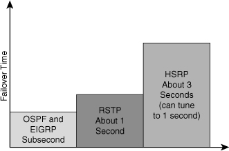
![]() The overall failover time in the data center is the combination of convergence at Layer 2, Layer 3, and Layer 4 components. Figure 5-3 shows failover times of high-availability protocols.
The overall failover time in the data center is the combination of convergence at Layer 2, Layer 3, and Layer 4 components. Figure 5-3 shows failover times of high-availability protocols.
![]() The network components have different recovery times:
The network components have different recovery times:
- Tuned routing protocols can failover in less than 1 second. Open Shortest Path First (OSPF) and Enhanced Interior Gateway Routing Protocol (EIGRP) can both achieve subsecond convergence time with recommended timer configurations.
- RSTP converges in about 1 second. RSTP permits subsecond convergence time for minor failures when logical ports are under watermarks and can take 1 second to 2 seconds for major failure conditions.
- EtherChannel can failover in approximately 1 second. When a link fails, Cisco EtherChannel technology redirects traffic from the failed link to the remaining links in less than 1 second.
- Default HSRP timers are 3 seconds for the hello time and 10 seconds for the hold time. A recommended practice is to configure the timers with a hello time of 1 second and a hold time of 3 seconds so that convergence occurs in less than 3 seconds. You can adjust the convergence time down to subsecond values, but you must consider the CPU load.
- Stateful service modules typically failover within 3 to 5 seconds. The convergence time for Cisco Catalyst 6500 Series Firewall Services Module (FWSM) is approximately 5 seconds with recommended timers, and the Caching Services Module (CSM) is approximately 5 seconds with recommended timers. Cisco Application Control Engine (ACE) can achieve failovers in approximately 1 second with its active/active configuration.
- The least tolerant TCP/IP stacks are the Windows Server and Windows XP client stacks, which have approximately a 9-second tolerance. Each of the TCP/IP stacks built into the various operating systems have a different level of tolerance for determining when a TCP session will drop. Other TCP/IP stacks such as those found in Linux, Hewlett-Packard (HP), and IBM systems are more tolerant and have a longer window before tearing down a TCP session.
Optimal Redundancy
![]() Providing optimal redundancy is important to ensure high availability. The key is not to provide too much redundancy resulting in an overly complicated or expensive to build and maintain network nor too little to compromise the required high availability.
Providing optimal redundancy is important to ensure high availability. The key is not to provide too much redundancy resulting in an overly complicated or expensive to build and maintain network nor too little to compromise the required high availability.
![]() As a recommended practice, the core and distribution layers are built with redundant switches and fully meshed links that provide maximum redundancy and optimal convergence, as shown in Figure 5-4. Access switches should have redundant connections to redundant distribution switches. The network bandwidth and capacity is engineered to withstand a switch or link failure, usually recovering within 120 ms to 200 ms. OSPF and EIGRP timer manipulation quickly attempts to redirect the flow of traffic away from a router that has experienced a failure toward an alternate path.
As a recommended practice, the core and distribution layers are built with redundant switches and fully meshed links that provide maximum redundancy and optimal convergence, as shown in Figure 5-4. Access switches should have redundant connections to redundant distribution switches. The network bandwidth and capacity is engineered to withstand a switch or link failure, usually recovering within 120 ms to 200 ms. OSPF and EIGRP timer manipulation quickly attempts to redirect the flow of traffic away from a router that has experienced a failure toward an alternate path.


![]() In a fully redundant topology with tuned IGP timers, adding redundant supervisors with Cisco NSF and SSO might cause longer convergence times than single supervisors with tuned IGP timers. NSF attempts to maintain the flow of traffic through a router that has experienced a failure. NSF with SSO is designed to maintain the link up with neighbors while preserving the routing capabilities during a routing convergence event.
In a fully redundant topology with tuned IGP timers, adding redundant supervisors with Cisco NSF and SSO might cause longer convergence times than single supervisors with tuned IGP timers. NSF attempts to maintain the flow of traffic through a router that has experienced a failure. NSF with SSO is designed to maintain the link up with neighbors while preserving the routing capabilities during a routing convergence event.
![]() In nonredundant topologies, using Cisco NSF with SSO and redundant supervisors can provide significant resiliency improvements.
In nonredundant topologies, using Cisco NSF with SSO and redundant supervisors can provide significant resiliency improvements.
Provide Alternate Paths
![]() Although dual distribution switches connected individually to separate core switches will reduce peer relationships and port counts in the core layer, this design does not provide sufficient redundancy. If a link or core switch failure occurs, traffic is dropped.
Although dual distribution switches connected individually to separate core switches will reduce peer relationships and port counts in the core layer, this design does not provide sufficient redundancy. If a link or core switch failure occurs, traffic is dropped.
![]() An additional link providing an alternative path to a second core switch from each distribution switch offers redundancy to support a single link or node failure, as shown in Figure 5-5. A link between the two distribution switches is needed to support summarization of routing information from the distribution layer to the core.
An additional link providing an alternative path to a second core switch from each distribution switch offers redundancy to support a single link or node failure, as shown in Figure 5-5. A link between the two distribution switches is needed to support summarization of routing information from the distribution layer to the core.
Avoid Too Much Redundancy
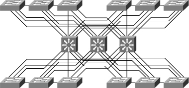
![]() In Figure 5-6, a third switch is added to the distribution switches in the center. This extra switch adds unneeded complexity to the design and leads to these design questions:
In Figure 5-6, a third switch is added to the distribution switches in the center. This extra switch adds unneeded complexity to the design and leads to these design questions:
- Where should the root switch be placed? With this design, it is not easy to determine where the root switch is located.
- What links should be in a blocking state? It is hard to determine how many ports will be in a blocking state.
- What are the implications of STP and RSTP convergence? The network convergence is definitely not deterministic.
- When something goes wrong, how do you find the source of the problem? The design is much harder to troubleshoot.
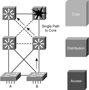
Avoid Single Point of Failure
![]() Avoiding single points of failure is another key element to high availability. If there is only one path to a device or a network, the loss of the path is unrecoverable. Redundancy is relatively easy to implement at the distribution or the core layers, where duplicate links and duplicate devices can exist to interconnect the other elements of the network. Redundancy is more difficult to achieve at the access layer. An access switch failure is a single point of failure that causes an outage for the end devices connected to it. You can reduce the outage to 1 to 3 seconds in this access layer by utilizing SSO in a Layer 2 environment or Cisco NSF with SSO in a Layer 3 environment, as shown in Figure 5-7.
Avoiding single points of failure is another key element to high availability. If there is only one path to a device or a network, the loss of the path is unrecoverable. Redundancy is relatively easy to implement at the distribution or the core layers, where duplicate links and duplicate devices can exist to interconnect the other elements of the network. Redundancy is more difficult to achieve at the access layer. An access switch failure is a single point of failure that causes an outage for the end devices connected to it. You can reduce the outage to 1 to 3 seconds in this access layer by utilizing SSO in a Layer 2 environment or Cisco NSF with SSO in a Layer 3 environment, as shown in Figure 5-7.


Cisco NSF with SSO
![]() Cisco NSF with SSO is a supervisor redundancy mechanism in Cisco IOS Software that enables extremely fast supervisor switchover at Layers 2 to 4. SSO enables the standby route processor (RP) to take control of the device after a hardware or software fault on the active RP. SSO synchronizes startup configuration, startup variables, and running configuration, as well as dynamic runtime data including Layer 2 protocol states for trunks and ports, hardware Layer 2 and Layer 3 tables (MAC, Forwarding Information Base [FIB], and adjacency tables) and ACLs and QoS tables. NSF with SSO is explained more in the supervisor redundancy section of this chapter.
Cisco NSF with SSO is a supervisor redundancy mechanism in Cisco IOS Software that enables extremely fast supervisor switchover at Layers 2 to 4. SSO enables the standby route processor (RP) to take control of the device after a hardware or software fault on the active RP. SSO synchronizes startup configuration, startup variables, and running configuration, as well as dynamic runtime data including Layer 2 protocol states for trunks and ports, hardware Layer 2 and Layer 3 tables (MAC, Forwarding Information Base [FIB], and adjacency tables) and ACLs and QoS tables. NSF with SSO is explained more in the supervisor redundancy section of this chapter.
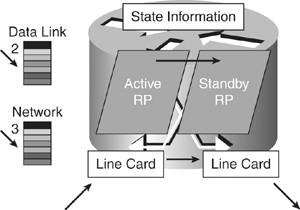
![]() Cisco NSF is a Layer 3 function that works with SSO to minimize the amount of time a network is unavailable to its users following a switchover. The main objective of Cisco NSF is to continue forwarding IP packets following an RP switchover, as shown in Figure 5-8. Cisco NSF is supported by the EIGRP, OSPF, Intermediate System-to-Intermediate System (IS-IS), and Border Gateway Protocol (BGP) for routing. A router running these protocols can detect an internal switchover and take the necessary actions to continue forwarding network traffic using CEF while recovering route information from the peer devices. With Cisco NSF, peer-networking devices continue to forward packets while route convergence completes and do not experience routing flaps.
Cisco NSF is a Layer 3 function that works with SSO to minimize the amount of time a network is unavailable to its users following a switchover. The main objective of Cisco NSF is to continue forwarding IP packets following an RP switchover, as shown in Figure 5-8. Cisco NSF is supported by the EIGRP, OSPF, Intermediate System-to-Intermediate System (IS-IS), and Border Gateway Protocol (BGP) for routing. A router running these protocols can detect an internal switchover and take the necessary actions to continue forwarding network traffic using CEF while recovering route information from the peer devices. With Cisco NSF, peer-networking devices continue to forward packets while route convergence completes and do not experience routing flaps.
Routing Protocols and NSF
![]() Cisco NSF enables for the continued forwarding of data packets along known routes while the routing protocol information is being restored following a switchover. With Cisco NSF, peer-Cisco NSF devices do not experience routing flaps because the interfaces remain up during a switchover and adjacencies do not reset. Data traffic is forwarded while the standby RP assumes control from the failed active RP during a switchover. User sessions established prior to the switchover are maintained.
Cisco NSF enables for the continued forwarding of data packets along known routes while the routing protocol information is being restored following a switchover. With Cisco NSF, peer-Cisco NSF devices do not experience routing flaps because the interfaces remain up during a switchover and adjacencies do not reset. Data traffic is forwarded while the standby RP assumes control from the failed active RP during a switchover. User sessions established prior to the switchover are maintained.
![]() The capability of the intelligent line cards to remain up through a switchover and kept current with the FIB on the active RP is crucial to Cisco NSF operation. While the control plane builds a new routing protocol database and restarts peering agreements, the data plane relies on pre-switchover forwarding-table synchronization to continue forwarding traffic.
The capability of the intelligent line cards to remain up through a switchover and kept current with the FIB on the active RP is crucial to Cisco NSF operation. While the control plane builds a new routing protocol database and restarts peering agreements, the data plane relies on pre-switchover forwarding-table synchronization to continue forwarding traffic.
| Note |
|
![]() After the routing protocols have converged, CEF updates the FIB table and removes stale route entries, and then it updates the line cards with the refreshed FIB information.
After the routing protocols have converged, CEF updates the FIB table and removes stale route entries, and then it updates the line cards with the refreshed FIB information.
![]() The switchover must be completed before the Cisco NSF dead and hold timers expire, or else the peers will reset the adjacency and reroute the traffic.
The switchover must be completed before the Cisco NSF dead and hold timers expire, or else the peers will reset the adjacency and reroute the traffic.
Implementing High Availability
![]() When designing a campus network, the network engineer needs to plan the optimal use of the highly redundant devices. Carefully consider when and where to invest in redundancy to create a resilient and highly available network.
When designing a campus network, the network engineer needs to plan the optimal use of the highly redundant devices. Carefully consider when and where to invest in redundancy to create a resilient and highly available network.
| Note |
|
Distributed VLANs on Access Switches
![]() If the enterprise campus requirements must support VLANs spanning multiple access layer switches, the design model uses a Layer 2 link for interconnecting the distribution switches, as shown in Figure 5-9. This design is more complex than the Layer 3 interconnection of the distribution switches. The Spanning Tree Protocol (STP) convergence process initiates for uplink failures and recoveries.
If the enterprise campus requirements must support VLANs spanning multiple access layer switches, the design model uses a Layer 2 link for interconnecting the distribution switches, as shown in Figure 5-9. This design is more complex than the Layer 3 interconnection of the distribution switches. The Spanning Tree Protocol (STP) convergence process initiates for uplink failures and recoveries.


![]() You should take the following steps to improve this suboptimal design:
You should take the following steps to improve this suboptimal design:
- Use Rapid STP (RSTP) as the version of STP.
- Provide a Layer 2 trunk between the two distribution switches to avoid unexpected traffic paths and multiple convergence events.
- Place the Hot Standby Router Protocol (HSRP) primary and the STP primary root on the same distribution layer switch if you choose to load balance VLANs across uplinks. The HSRP and RSTP root should be colocated on the same distribution switches to avoid using the interdistribution link for transit.
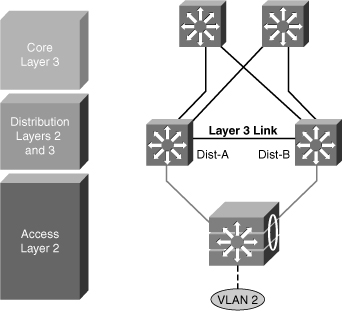
Local VLANs on Access Switches
![]() In this time-proven topology, no VLANs span between access layer switches across the distribution switches, as shown in Figure 5-10. A subnet equals a VLAN that, in turn, equals an access switch because VLAN is restricted to one access switch only. The root for each VLAN is aligned with the active HSRP instance. From a STP perspective, both access layer uplinks are forwarding, so the only convergence dependencies are the default gateway and return-path route selection across the distribution-to-distribution Layer 3 link.
In this time-proven topology, no VLANs span between access layer switches across the distribution switches, as shown in Figure 5-10. A subnet equals a VLAN that, in turn, equals an access switch because VLAN is restricted to one access switch only. The root for each VLAN is aligned with the active HSRP instance. From a STP perspective, both access layer uplinks are forwarding, so the only convergence dependencies are the default gateway and return-path route selection across the distribution-to-distribution Layer 3 link.


| Note |
![]() With this design, a distribution-to-distribution Layer 3 link is required for route summarization. A recommended practice is to map the Layer 2 VLAN number to the Layer 3 subnet for ease of use and management.
With this design, a distribution-to-distribution Layer 3 link is required for route summarization. A recommended practice is to map the Layer 2 VLAN number to the Layer 3 subnet for ease of use and management.
Layer 3 Access to the Distribution Interconnection
![]() In this time-proven topology, no VLANs span between access layer switches across the distribution switches, as shown in Figure 5-11. A subnet equals a VLAN that, in turn, equals an access switch. The root for each VLAN is aligned with the active HSRP instance. From a STP perspective, both access layer uplinks are forwarding, so the only convergence dependencies are the default gateway and return-path route selection across the distribution-to-distribution link.
In this time-proven topology, no VLANs span between access layer switches across the distribution switches, as shown in Figure 5-11. A subnet equals a VLAN that, in turn, equals an access switch. The root for each VLAN is aligned with the active HSRP instance. From a STP perspective, both access layer uplinks are forwarding, so the only convergence dependencies are the default gateway and return-path route selection across the distribution-to-distribution link.


![]() With this design as well, a distribution-to-distribution Layer 3 link is required for route summarization. A recommended practice is to map the Layer 2 VLAN number to the Layer 3 subnet for ease of use and management.
With this design as well, a distribution-to-distribution Layer 3 link is required for route summarization. A recommended practice is to map the Layer 2 VLAN number to the Layer 3 subnet for ease of use and management.
Daisy Chaining Access Layer Switches
![]() In the topology shown in Figure 5-12 before failures, no links block from a STP or RSTP perspective. Both uplinks are available to actively forward and receive traffic. Both distribution nodes can forward return-path traffic from the rest of the network toward the access layer for devices attached to all members of the stack or chain.
In the topology shown in Figure 5-12 before failures, no links block from a STP or RSTP perspective. Both uplinks are available to actively forward and receive traffic. Both distribution nodes can forward return-path traffic from the rest of the network toward the access layer for devices attached to all members of the stack or chain.


![]() Two scenarios can occur if a link or node in the middle of the chain or stack fails. In the first case, the standby HSRP peer (Dist-B) can go active as it loses connectivity to its primary peer (Dist-A), forwarding traffic outbound for the devices that still have connectivity to it. The primary HSRP peer remains active and also forwards outbound traffic for its half of the stack. Although this is not optimum, it is not detrimental from the perspective of outbound traffic.
Two scenarios can occur if a link or node in the middle of the chain or stack fails. In the first case, the standby HSRP peer (Dist-B) can go active as it loses connectivity to its primary peer (Dist-A), forwarding traffic outbound for the devices that still have connectivity to it. The primary HSRP peer remains active and also forwards outbound traffic for its half of the stack. Although this is not optimum, it is not detrimental from the perspective of outbound traffic.
![]() Another scenario, as shown in Figure 5-13, illustrates the issue with this design for the return traffic. The core switch sees both the distribution layer switches advertise the VLAN 2 subnet and does equal cost load balancing for the traffic destined to VLAN 2 to both the Dist-A and Dist-B. Therefore, return-path traffic has a 50 percent chance of arriving on a distribution switch that does not have physical connectivity to the half of the stack where the traffic is destined. The traffic that arrives on the wrong distribution switch is dropped.
Another scenario, as shown in Figure 5-13, illustrates the issue with this design for the return traffic. The core switch sees both the distribution layer switches advertise the VLAN 2 subnet and does equal cost load balancing for the traffic destined to VLAN 2 to both the Dist-A and Dist-B. Therefore, return-path traffic has a 50 percent chance of arriving on a distribution switch that does not have physical connectivity to the half of the stack where the traffic is destined. The traffic that arrives on the wrong distribution switch is dropped.


![]() The solution to this issue with this design is to provide alternative connectivity across the stack in the form of a direct connection between the Access-a and Access-c switches in the stack. This link needs to be carefully deployed so that the appropriate STP behavior occurs in the access layer if the stack is greater than three switches. It is preferred to implement StackWise access switches, which is explained in the next section.
The solution to this issue with this design is to provide alternative connectivity across the stack in the form of a direct connection between the Access-a and Access-c switches in the stack. This link needs to be carefully deployed so that the appropriate STP behavior occurs in the access layer if the stack is greater than three switches. It is preferred to implement StackWise access switches, which is explained in the next section.
![]() An alternative design uses a Layer 2 link between the distribution switches.
An alternative design uses a Layer 2 link between the distribution switches.
StackWise Access Switches
![]() StackWise technology in the access layer supports the recommended practice of using a Layer 3 connection between the distribution switches without having to use a loopback cable or perform extra configuration, as shown in Figure 5-14.
StackWise technology in the access layer supports the recommended practice of using a Layer 3 connection between the distribution switches without having to use a loopback cable or perform extra configuration, as shown in Figure 5-14.
![]() The true stack creation provided by the Cisco Catalyst 3750 Series switches makes using stacks in the access layer much less complex than chains or stacks of other models. A stack of 3750 switches appears as one node from the network topology perspective.
The true stack creation provided by the Cisco Catalyst 3750 Series switches makes using stacks in the access layer much less complex than chains or stacks of other models. A stack of 3750 switches appears as one node from the network topology perspective.
Too Little Redundancy
![]() Figure 5-15 shows a less than optimal design where VLANs span multiple access layer switches. Without a Layer 2 link between the distribution switches, the design is a looped Figure-8 topology. One access layer uplink will be blocking. HSRP hellos are exchanged by transiting the access switches.
Figure 5-15 shows a less than optimal design where VLANs span multiple access layer switches. Without a Layer 2 link between the distribution switches, the design is a looped Figure-8 topology. One access layer uplink will be blocking. HSRP hellos are exchanged by transiting the access switches.


![]() Initially, traffic is forwarded from both access switches to the Distribution A switch that supports the STP root and the primary or active HSRP peer for VLAN 2. However, this design will black-hole traffic and be affected by multiple convergence events with a single network failure.
Initially, traffic is forwarded from both access switches to the Distribution A switch that supports the STP root and the primary or active HSRP peer for VLAN 2. However, this design will black-hole traffic and be affected by multiple convergence events with a single network failure.
![]() As shown in Figure 5-16, when the uplink from Access A switch to the Distribution A switch fails, there are three convergence events:
As shown in Figure 5-16, when the uplink from Access A switch to the Distribution A switch fails, there are three convergence events:
- Access A switch sends traffic across its active uplink to Distribution B switch to get to its default gateway. The traffic is black-holed at Distribution B switch because Distribution B switch does not initially have a path to the primary or active HSRP peer on Distribution A switch due to the STP blocking. The traffic is dropped until the standby HSRP peer takes over as the default gateway after not receiving HSRP hellos from Distribution A switch.
Note With aggressive HSRP timers, you can minimize this period of traffic loss to approximately 900 ms. - The indirect link failure is eventually detected by Access B switch after the maximum-age (max_age) timer expires, and Access B switch removes blocking on the uplink to Distribution B switch. With standard STP, transitioning to forwarding can take as long as 50 seconds. If BackboneFast is enabled with Per VLAN Spanning Tree Plus (PVST+), this time can be reduced to 30 seconds, and RSTP can reduce this interval to as little as 1 second.
- After STP and RSTP converge, the distribution nodes reestablish their HSRP relationships, and Distribution A switch (the primary HSRP peer) preempts. This causes yet another convergence event when Access A switch end points start forwarding traffic to the primary HSRP peer. The unexpected side effect is that Access A switch traffic goes through Access B switch to reach its default gateway. The Access B switch uplink to Distribution B switch is now a transit link for Access A switch traffic, and the Access B switch uplink to Distribution A switch must now carry traffic for both the originally intended Access B switch and for Access A switch.


0 comments
Post a Comment